As part of my project to port the BrewPi firmware to the ESP8266 I decided to create an enclosure to tie everything together.
The case comes in two parts – a lid (which holds the LCD display) and a base (which holds everything else).
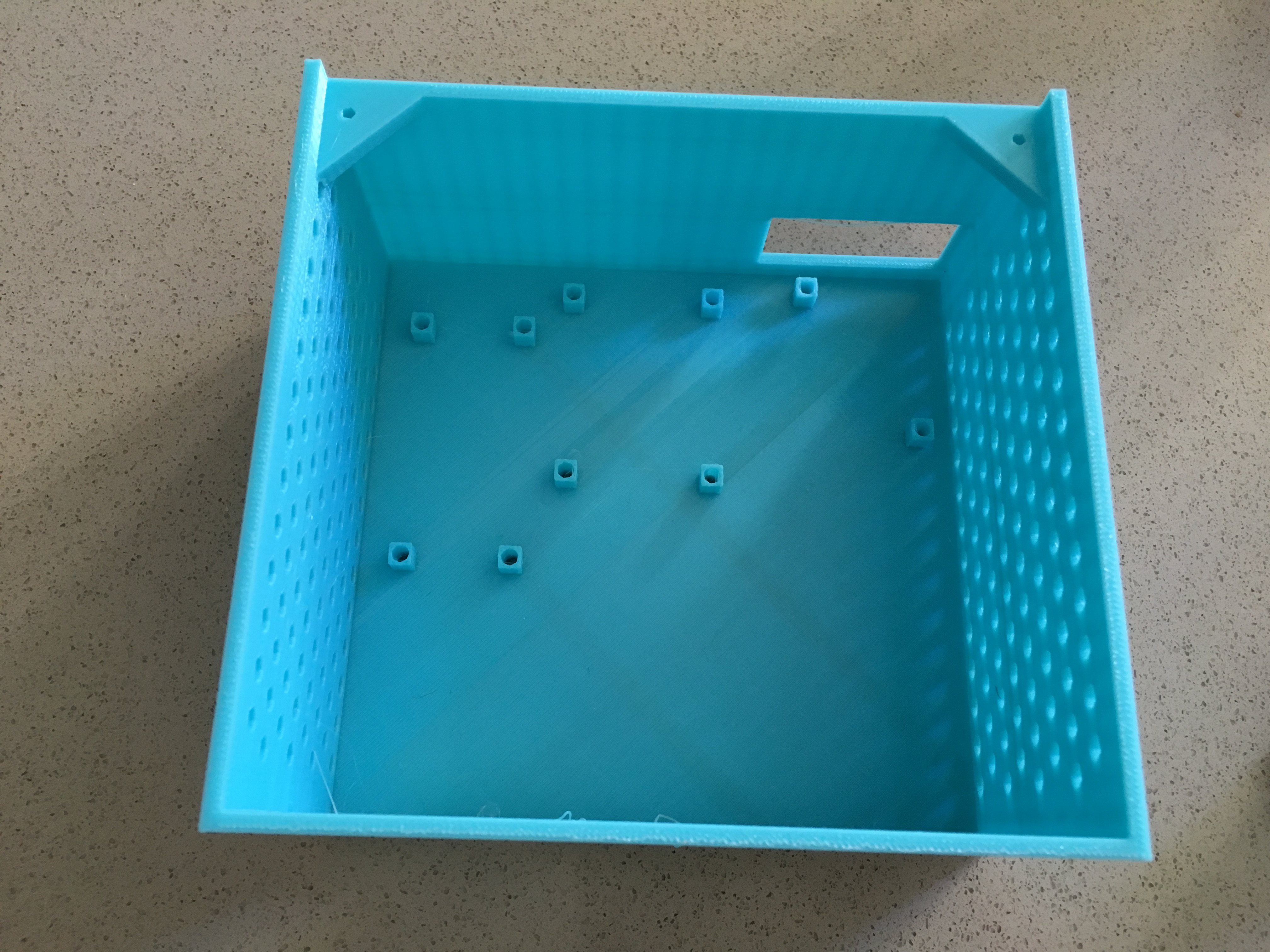
This enclosure isn’t perfect – the overhang on the AC plugs is rough without supports, and the PCB could use an additional support post underneath it (even though there aren’t screw holes) — but when assembled, it works great!
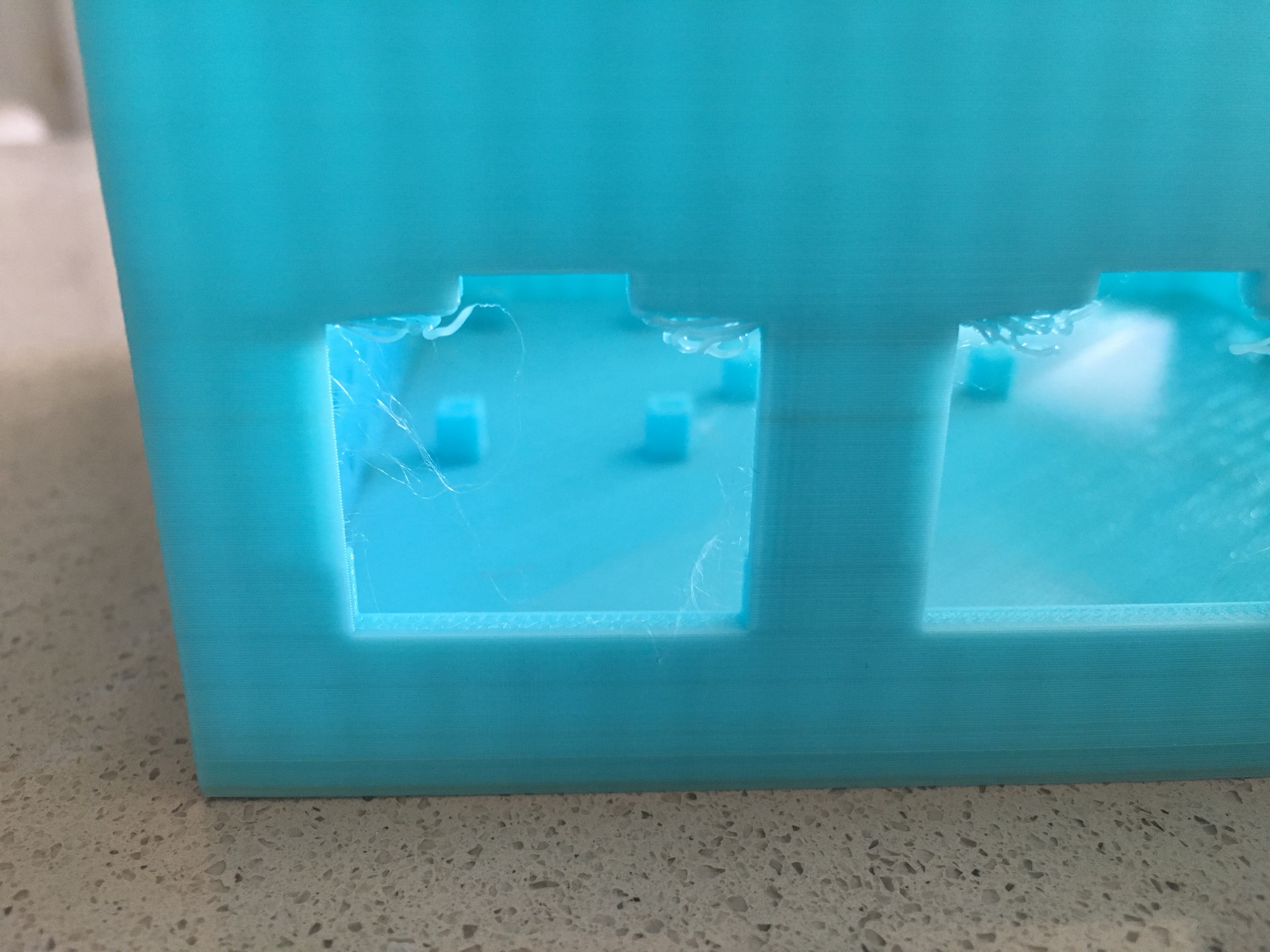
The models are posted on Thingiverse here and can be printed on most 3D printers. I recommend printing at a minimum resolution of 0.20mm to ensure the supports in the base print correctly.
Bill of Materials for the complete build is as follows:
- 14x #4-40 Philips Head Machine Screws
- 14x #4-40 Hex Nuts (Nylon not required)
- 2x #4-24 Philips Head Sheet Metal Screws
- 1x BrewPi/ESP8266 PCB (assembled)
- 1x WeMos D1 Mini v2/Pro
- 1x I2C/IIC LCD2004 LCD Display
- 1x 5v 2a Power Supply
- 1x 2-Channel Relay Board
- 8x Female-Female Dupont Wires
- 2x SS-6B Snap In AC Connectors
- 1x IEC-320 Male Power Inlet
- 9x Female Nylon Spade Quick-Connect Connectors (Optional)
- Black, Green, and White Wire
- Wire Nuts
- 4x Self-adhesive Rubber feet
Hi Thorrak
Thanks for putting this together
Would it be possible to do a version without the 2x SS-6B Snap In AC Connectors as these are not compatible with a lot of European socket versions.
May i suggest just a hole for the iec connector and the rest of the panel blank so the user can cut their own holes.
Many thanks for all your work on this
I’ve got another version that I need to post soon that uses standard US outlet connectors. I would imagine that something similar could be done for European-style outlets as well by editing the OpenSCAD files.
As far as leaving the rest of the panel blank, unfortunately I don’t think that would work with most 3D printed boxes. The problem you have is that most of the time the wall is mostly hollow, so it would be prone to shattering when you tried to drill out the holes.